Richard Folwell - GWR King Class - King Edward II
29/09/2023
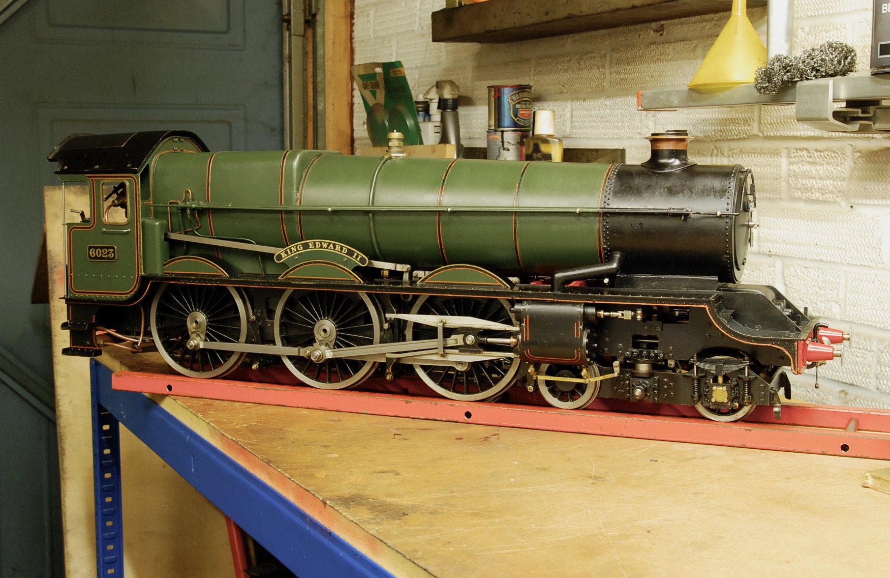
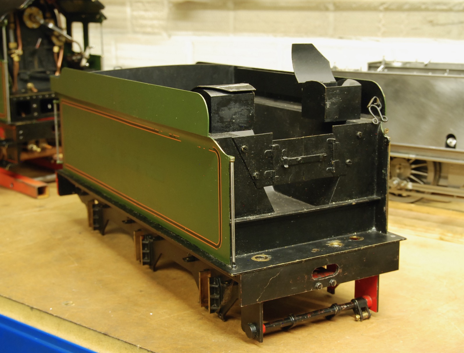
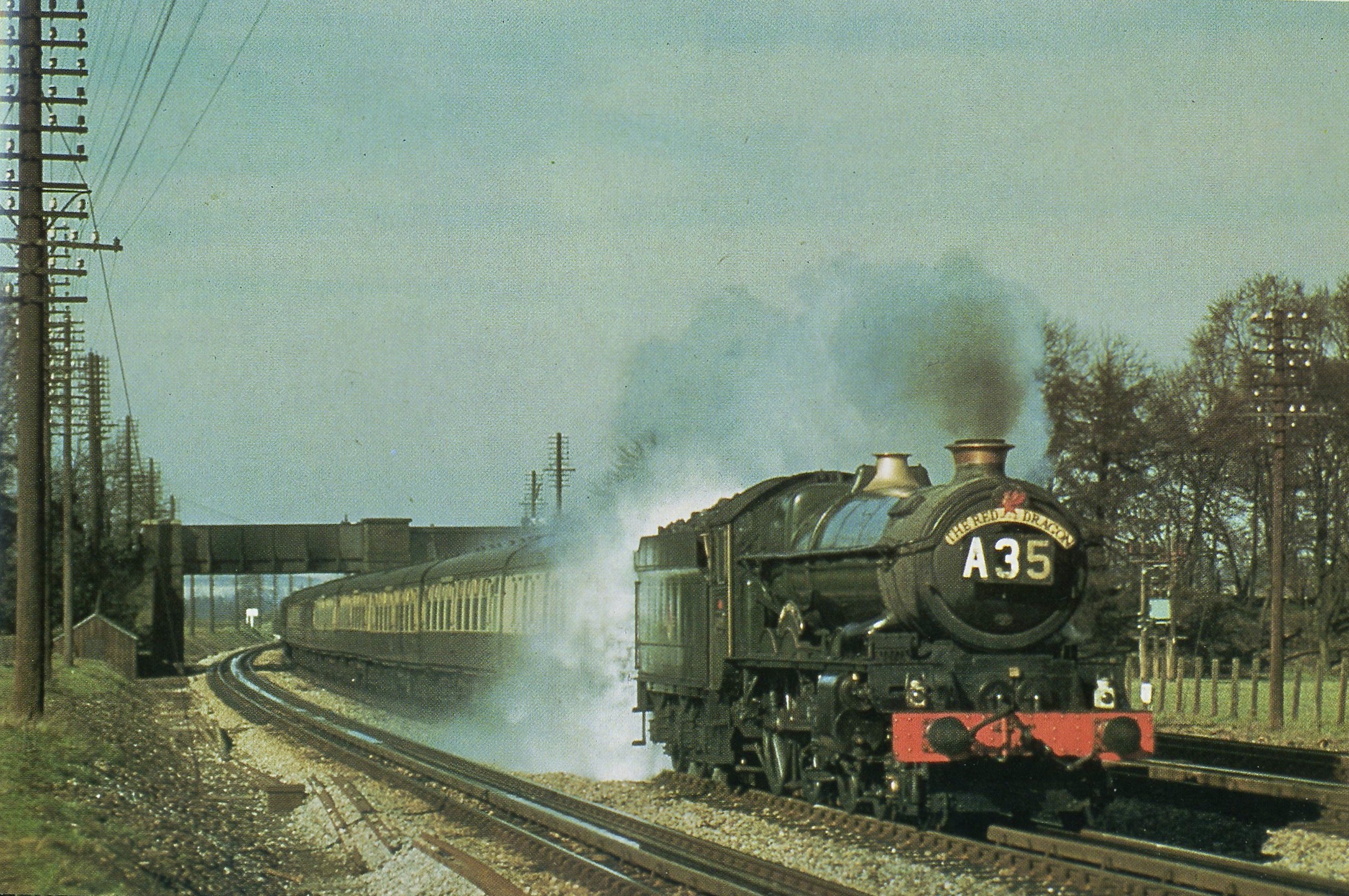
Greetings everyone, allow me to introduce my recent acquisition, King
Edward II, herein referred to as KE2. A 3 1/2" gauge example of the
Great Western's flagship locomotive class.
At one time the King's were deemed the most powerful 4-6-0's in the
country and in keeping with the prototype this model has the full 4
cylinders with inside Walschaert's valve gear driving the outside valves
via rocker-arms exactly as per full-size. This miniature example was
built to the H. P. Jackson drawings/castings as marketed by Clarkson's
of York until that company's demise and now happily available again from
Blackgates Engineering.
I saw KE2 on the Station Road Steam website about a year ago, complete
with a video of it running on a rolling road and looking every inch a
Monarch. I thought "that is very, very nice" and kept looking every week
to find it hadn't sold and all the time my desire for this beauty was
growing. After 12 months or so they reduced the price and this was the
catalyst I needed to make my move. I contacted SRS and after a barrage
of questions from yours truly a deal was struck and she was mine!
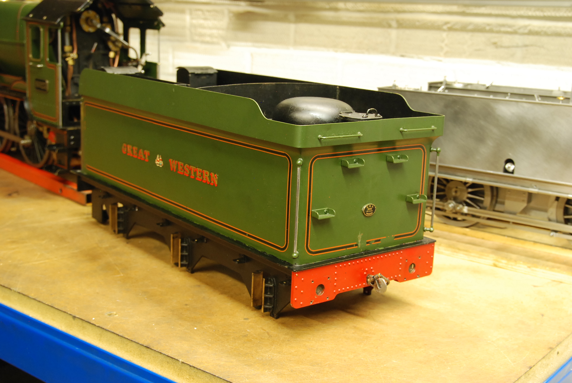
Now SRS described KE2 as being a 'running restoration', that is to say
working but needing attention. The safety-valve accumulated and wouldn't
pass a steam test, the injector was 'temperamental', which is one way of
saying it doesn't work, and the tender was in need of 'reassembly'.
The tender came with two chassis, one being the plain H. P. Jackson
design and the second a close to scale version with correct pattern
axle-boxes, working leaf-springs and folded steel channel stays and
bracketry as per Swindon drawings. It looked great but was incredibly
flimsy and I doubt it would stand up to the stresses and strains of
running out on the track. To further complicate matters the 'plain'
chassis had an axle-box missing and as Sod's Law dictates the plain
'boxes were considerably wider than the scale ones. So the decision has
been taken to persevere with the 'scale' chassis. The first task was to
remove the flimsy stays etc. and make up some new ones fit for purpose.
The chassis is now very rigid. The axle boxes were too good a fit in
their horns and the flanges have been eased to allow the axles to move
more freely to accommodate less than perfect track. The tender tank was
originally fitted to the 'plain' chassis and will need new pipework to
the drag beam, and a whole host of other modifications, in order to
marry the two together.
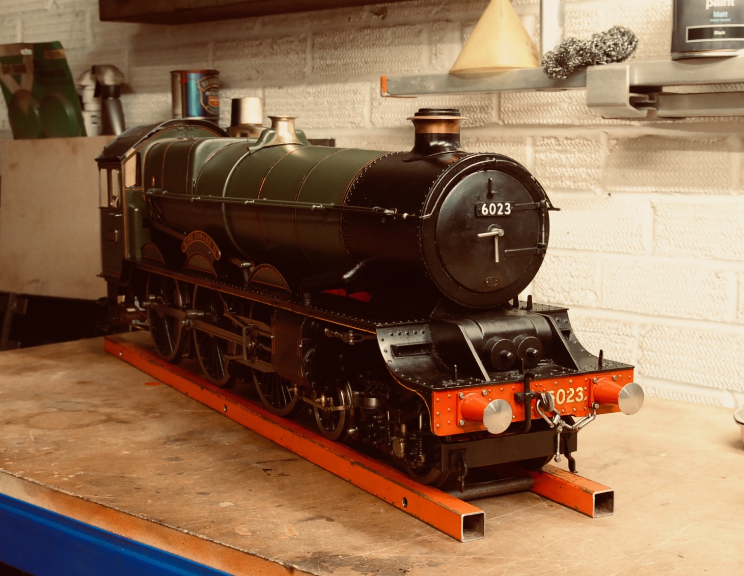
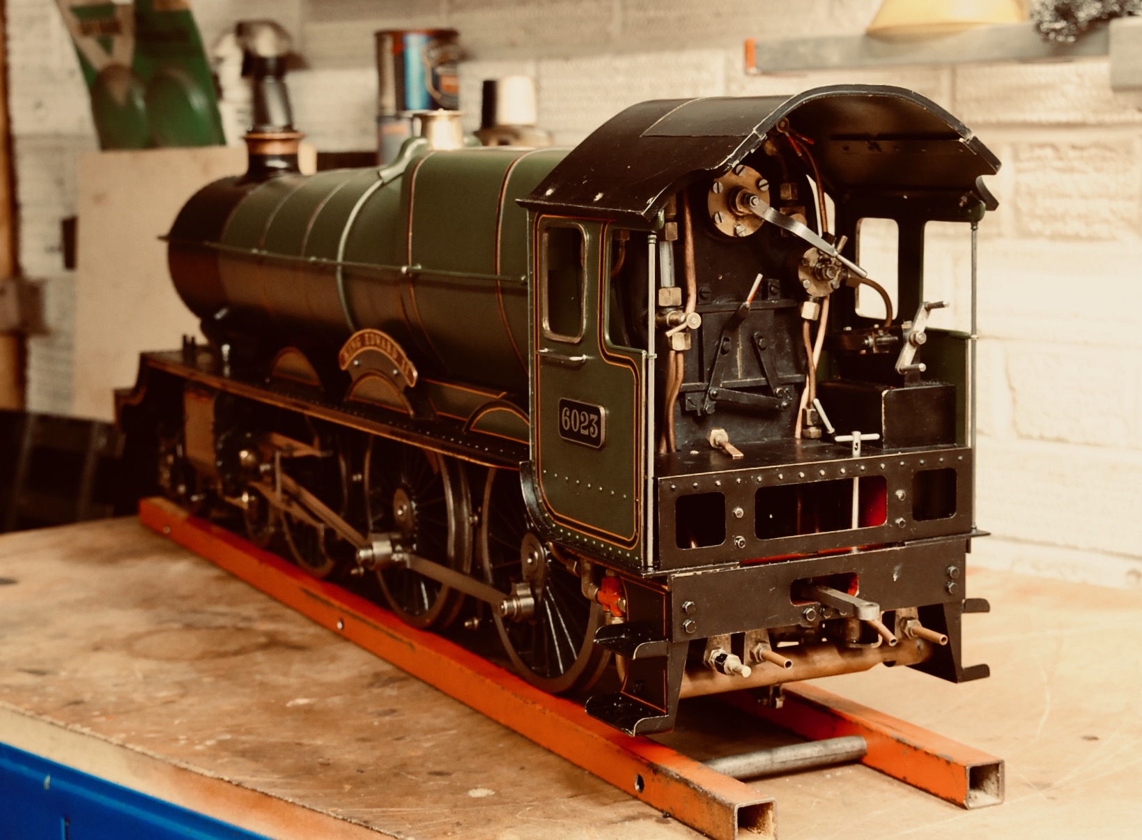
As for the locomotive it is very well made. There is virtually no
detectable wear on the motion parts and a few extra details have been
added, although there are still further additions I would like to make.
However, the priority is to get KE2 up and running and the boiler
certificated. KE2 has come with a full boiler history and paperwork
going back to it's two-times shell-test in 1988. The water capacity is
3.5 litres with a working pressure of 90 psi. Boiler water-feed is
provided by a tender hand-pump, axle driven pump and one injector (I
shall replace the original injector with a new one). SRS also provided
their own current hydraulic test certificate but just to be certain I've
tested it myself up to 135 psi and apart from a small leak from a clack
all seems fine.
So there you have it for now. After shaking down any problems I shall
bling it up with some extra detailing and repaint it in early British
Railways livery, which will be green and not that hideous blue the
preserved KE2 is finished in. I only hope that after lavishing all this
love and attention on the project it will perform in a manner fit for a
King and not turn out to be a Richard the Third!
11/11/2023
Work is now fully underway regarding the King project. Firstly the
paintwork. Everything on the tender chassis had been painted black and
falls into three categories: badly scratched, flaking off and sprayed
during the height of a sandstorm. The flaking off was due to all edges
on the chassis and its components having dead sharp edges and it could
be seen how the paint had failed to adhere at these points. There was
nothing for it - it all had to come off!
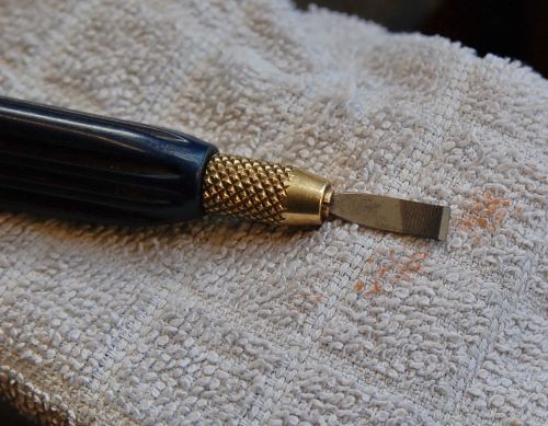
After consulting the Tuesday gang, and being warned off from using
paint-stripper, a shot-blaster would have been useful but I don't have
one, so the only option available was to scrape it off. To this end a
broken needle-file had a chisel-edge ground on it, as can be seen, and
this made relatively light work of paint removal. The scraper was used
in conjunction with a fibre-glass scratch-pen with a 2mm filament to get
into all the nooks and crannies. Paint removal complete, all the nasty
sharp edges were removed with a file.
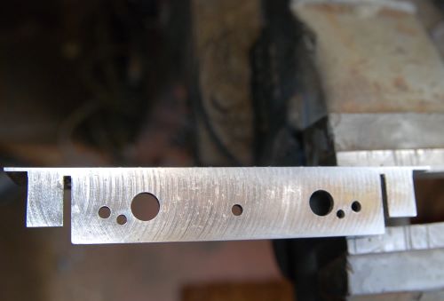
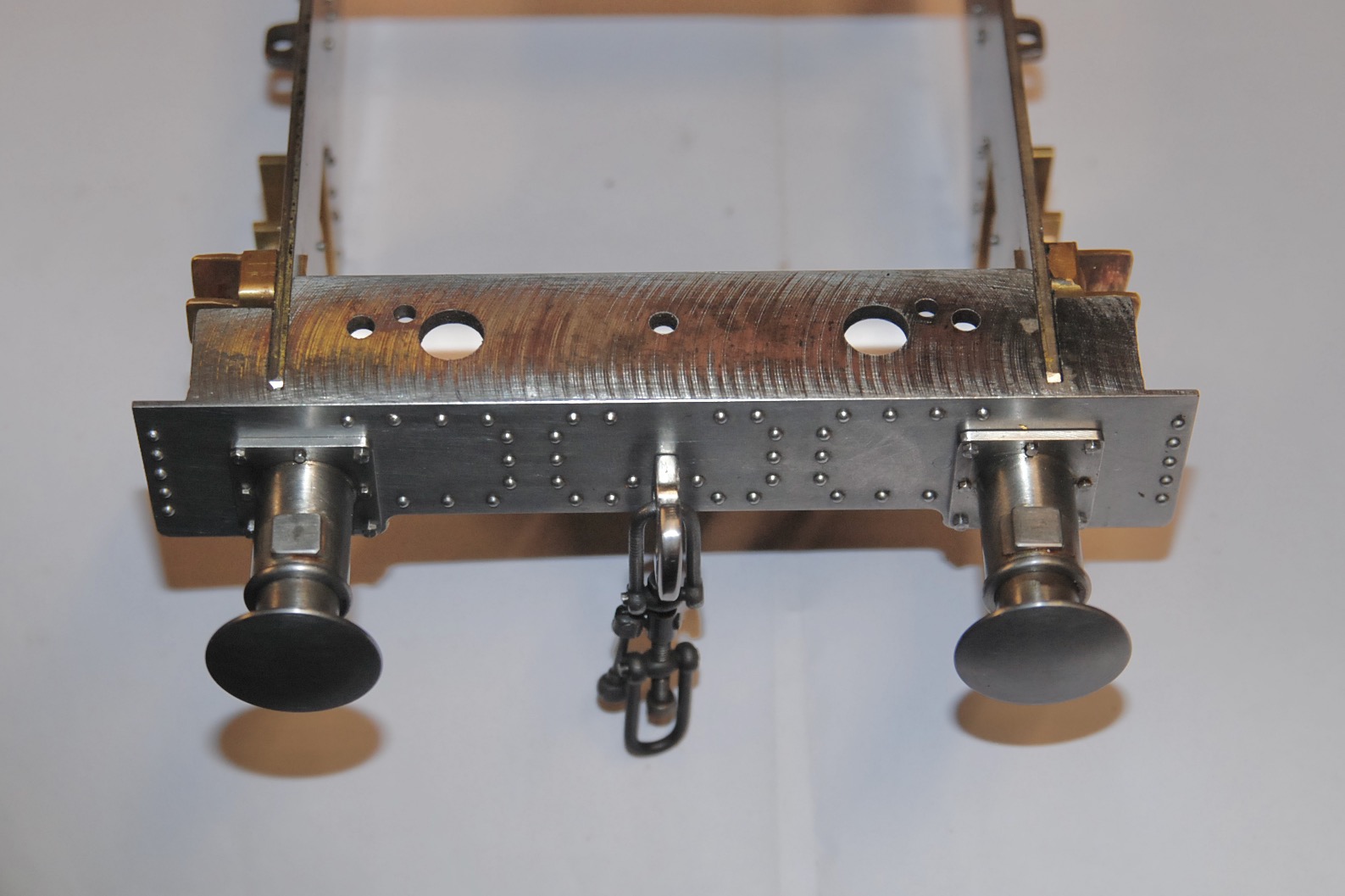
Now the paint was incredibly thick in places which tended to obscure
details such as rivet heads etc. During removal it was pleasing to find
that the horn-guides were in actual fact brass fabrications and not the
usual castings, but it also revealed some heavy machining marks on the
buffer beam caused by a large diameter cutter. Luckily the rivets had
not been fitted to the beam so it was easy, although time consuming, to
remove said marks with files and emery producing a nice smooth finish
(you can see the difference between untreated and treated faces). The
riveting was then undertaken. Had this beam already been riveted I would
have binned it!
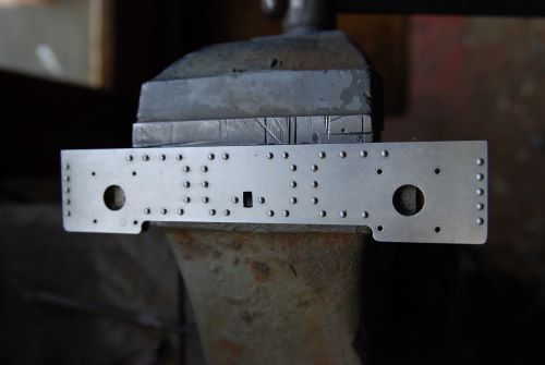
There were a couple of holes along the top edge of the frames which
serve no purpose and so these were filled. The method used here was to
tap them out the nearest available size, in this instance 5BA, then
Loctite in a couple of screws and after leaving overnight to cure filed
down smooth and as the photos show are now virtually undetectable. I
have a tin of less than perfect bolts/srews/studs kept specifically for
filling 'less than perfect holes' (or cock-ups if you prefer) as you
don't want to waste nice prime examples if you can help it.
I mentioned last time that the 'scale' chassis stays weren't up to the
job and they were replaced with stays more suited to the task. They can
be seen here as just simple lengths of flat bar, drilled, tapped and
screwed in from outside with csk-head screws. These will be filled over
at the repainting stage.
So that's where we're at. Although it doesn't look much it took ages to
remove that damn paint but as previously stated - it had to be done. The
current 'work in progress' is the drag-beam which should be done this
coming week and I'll report on that in due course.
16/11/2023
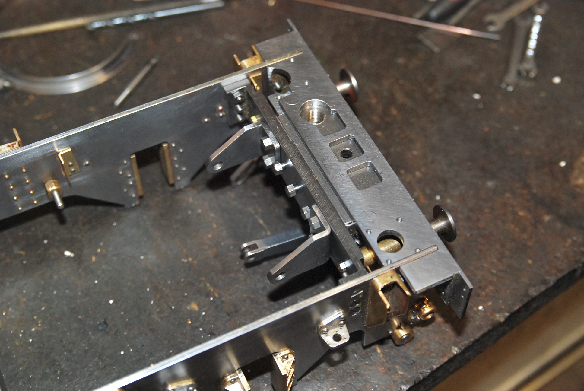
This time the drag-beam gets attention. Both this and the buffer-beam
follow traditional model-engineering design with both being made from
steel angle, which is surprising considering how the builder had
followed full-size practice with the stays etc. A fabricated drag-box
with a 'plank' beam would have been preferable but apart from scrapping
the originals and remaking them both from scratch then this is what
we're stuck with. The flimsy stays and brackets were removed from the
rear face of the beam which left just the basic angle to work with.
|
|
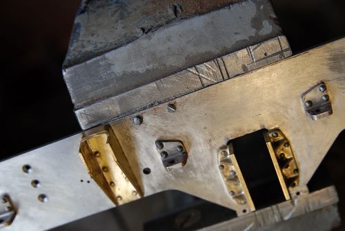
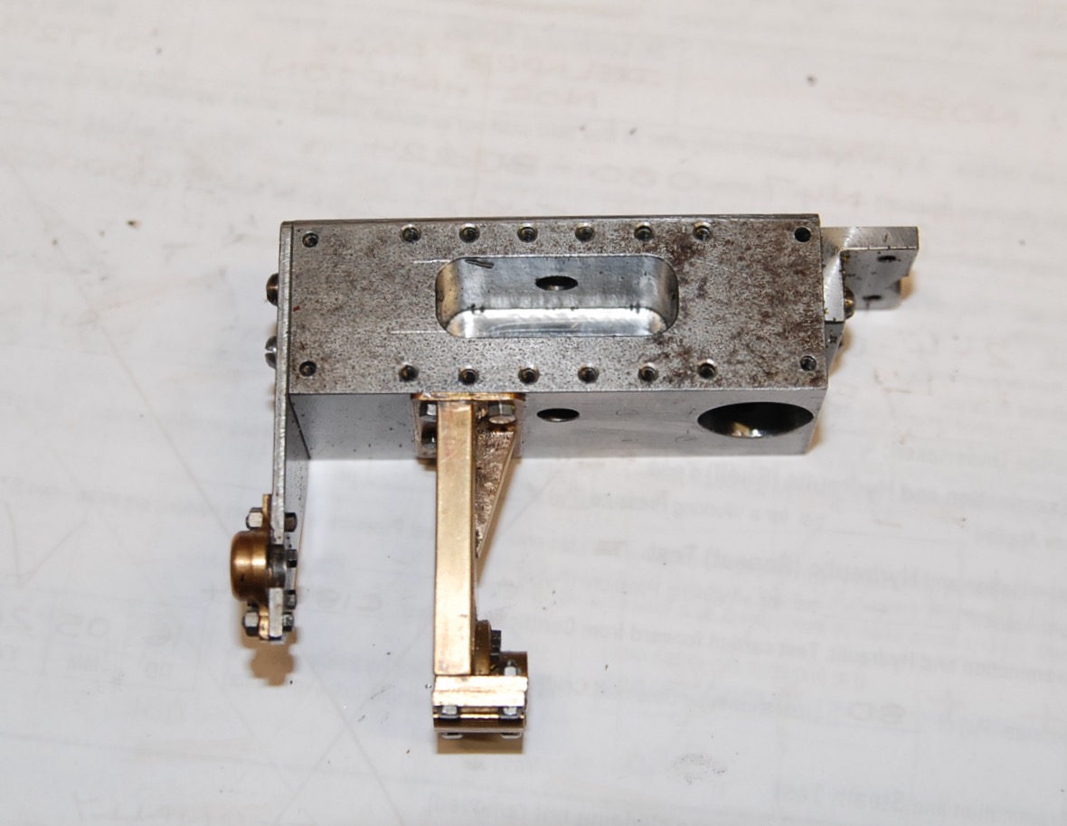
Two thin folded sections were originally bolted to the beam above and
below the front slot to provide a location for the loco/tender
coupling-link and pin. These sections have been replaced with a solid
block pocketed out to accept the link and bolted to the angle using the
pre-existing holes. This block was machined to the same overall
dimensions as the original bracketry to minimise complication when
fitting the brass fabbed brake-shaft support bracket, seen on the bottom
face just off-centre, and the inner water-scoop operating-shaft bearing
bracket fixed to the end. The outer water-scoop shaft bearing is fixed
to the right-hand chassis frame, and lastly the large tapped and
counterbored hole to the right of the block will be used to mount the
injector water-valve when the time comes.
Now the builder had gone to the trouble of providing loco/tender
buffers, which in locomotives of this scale, not having slotted
coupling-links, are totally unnecessary, but the components were there
so it would have been wasteful not to retain them. Sadly though the
buffer shanks ran directly in the steel angle with the thin brass
end-plates being purely for appearance. This resulted in a 'rough'
action when the buffers were depressed and so this poor state of affairs
had to be remedied. The holes in the beam were opened up slightly to
allow the fitting of one-piece housings machined from brass and the
buffers are now silky smooth in operation. The springs are very
light-duty and a photograph shows the buffers, brass housings and
springs plus the two original brass front-plates.
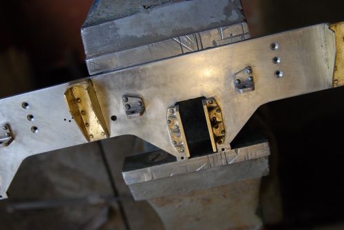
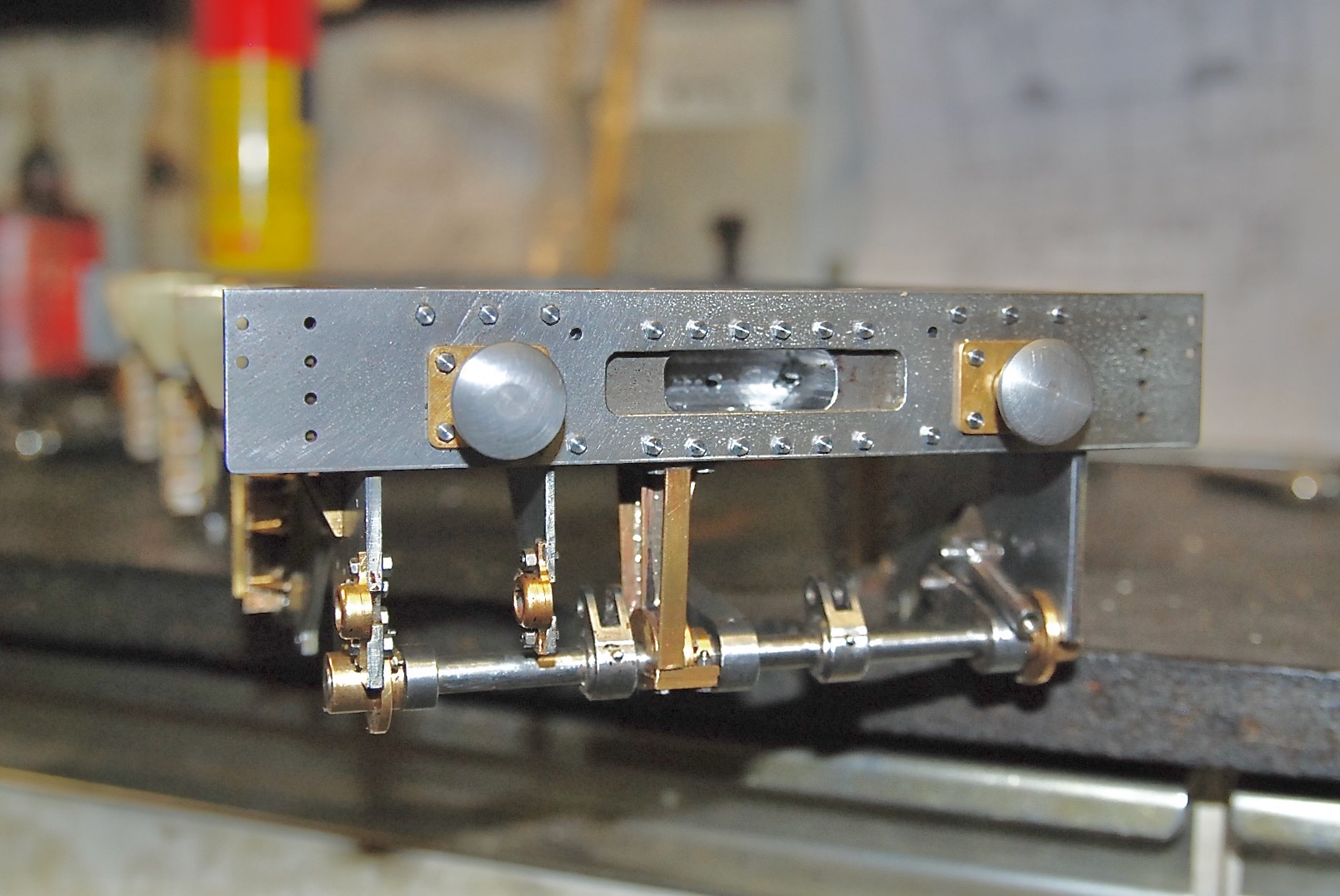
Close inspection of the actual drag-beam angle showed that the smaller
fixing brackets, used for bolting the beam to the frames, were only
lightly riveted to the main drag-beam with three 3/64" rivets and was
considered a weak point. Due to space constraints it was not possible to
'beef' this up and so an auxiliary frame-spacer was machined to fit
directly behind the drag-beam assembly which then enabled a bolted
fixing through the spacer and into tapped holes in the rear of the solid
coupling-block; now that beam ain't going anywhere! Not only does this
extra frame-spacer result in an incredibly strong beam fixing but also
provides a flat surface for the buffer spindle retaining nuts to bear
against and also a mounting for the two folded angle-brackets which will
be used for locating the brake-cylinder. There are three extra bolts
between the brake-cylinder brackets which will eventually fix the
water-pipe support bracket.
|
|
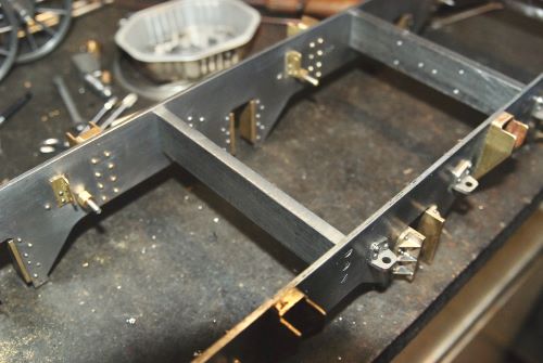
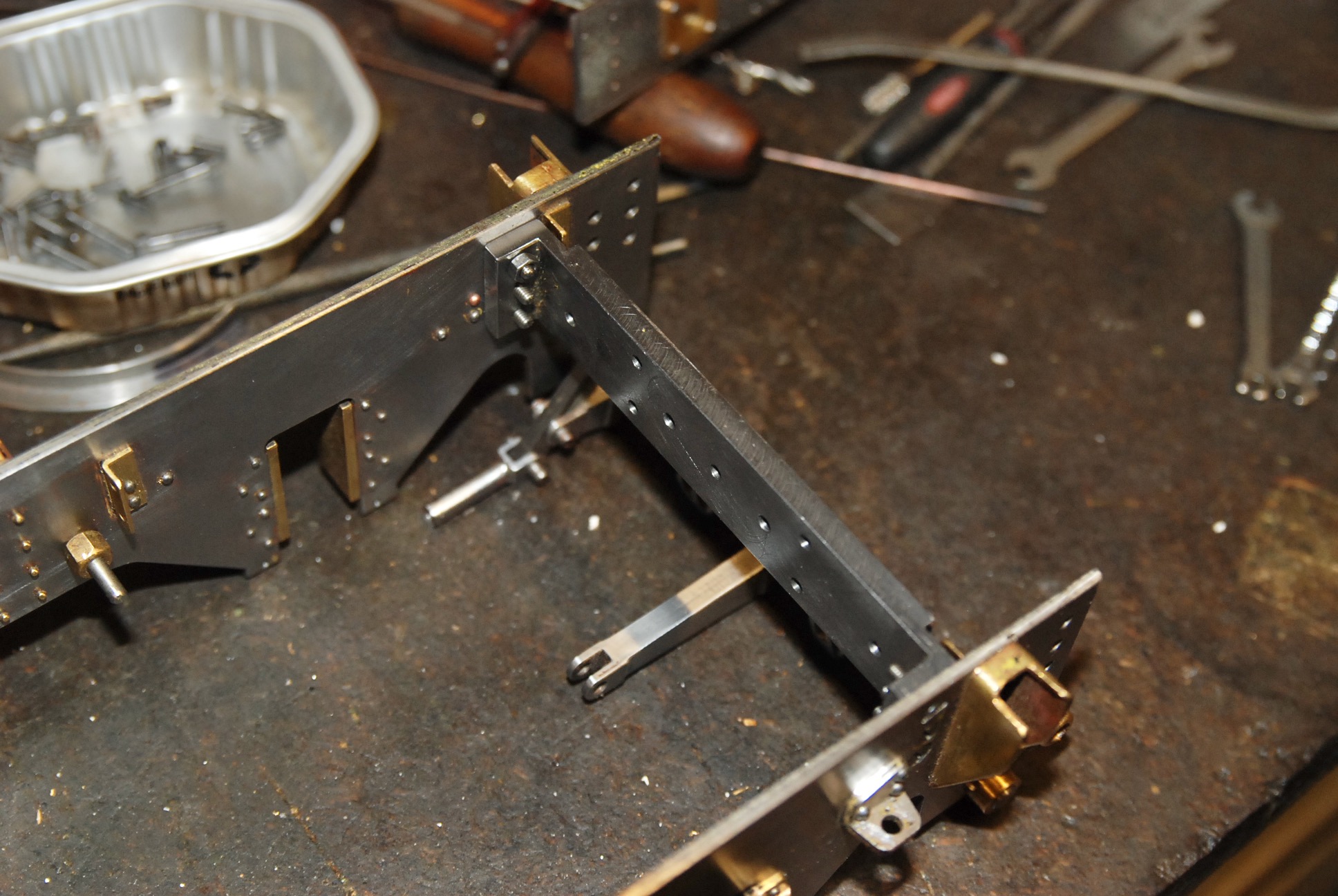
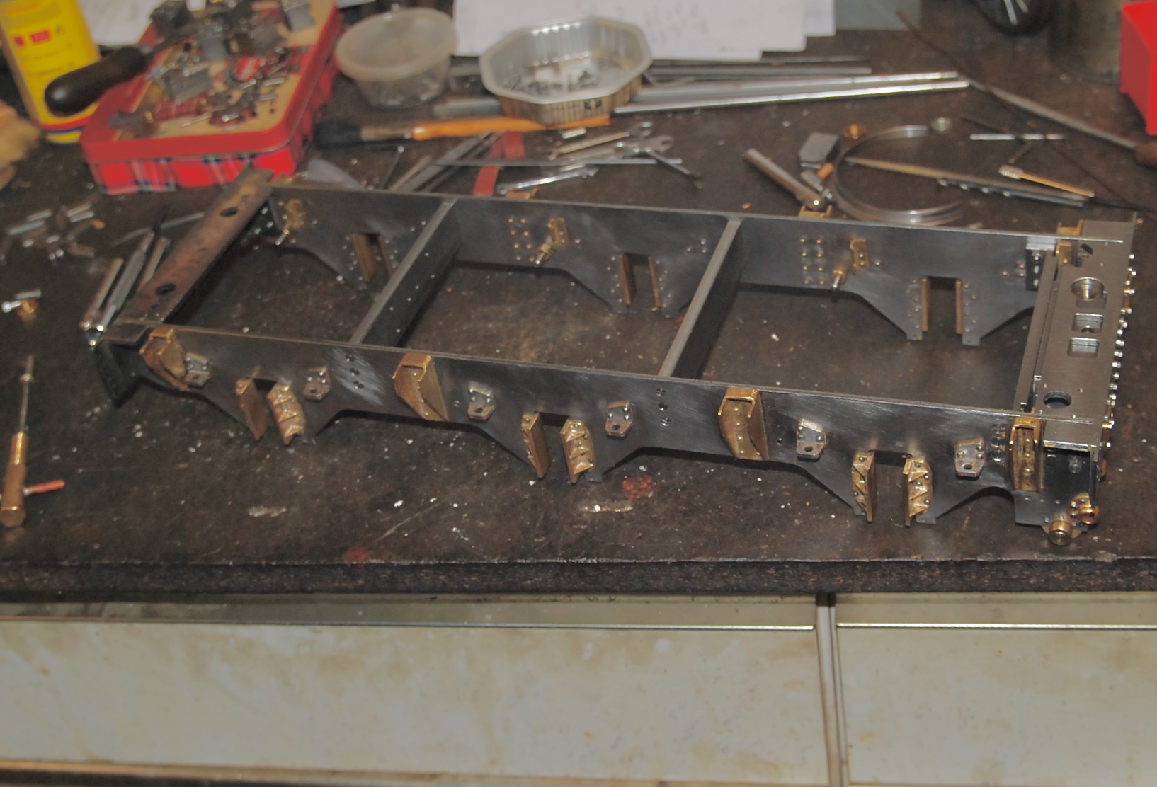
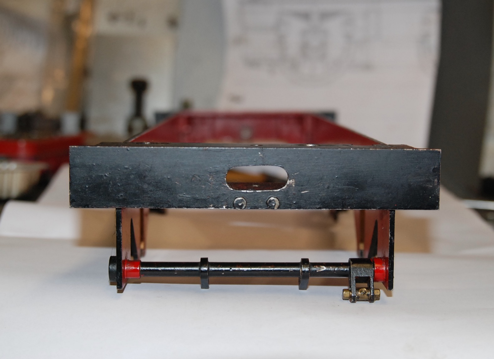
All this having been done the basic chassis structure is now re-erected
and complete after what seems an eternity. It's been a lot of work but
well worth it and I've included a couple of photos showing the
drag-beams of both the original 'plain' tender chassis and the closer to
scale version; I know which I prefer!
|
|
23/11/2023
After showing the front buffers last time it's now the turn of the rear
ones. The 'scale' chassis had arrived without any rear buffers but the
'plain' chassis had, plus the 'scale' buffer-beam had been pre-drilled
ready to accept them, or so I thought. After removing said buffers it
was found that the holes didn't match up and they couldn't be used
without a lot of faffing about. "Oh-dear", I muttered to myself, but
then as the saying goes "as one door closes another one opens" and the
fact that the buffers wouldn't fit provided the incentive to make a
completely new pair. You see the tapered stocks/bodies of these buffers
are incorrect for this tender. The correct pattern have parallel stocks
with a larger diameter head.
Now I doubt many people have ever considered buffer design, and even
though these 'percussion absorption devices' all do exactly the same job
they actually come in all shapes and sizes. The heads can be large,
small, round or oval. The stocks short, long, tapered, straight,
different diameters and tapers on the same stock or even just plain
wooden blocks. One anomaly with the King class locos is that the
locomotives themselves had the tapered stock variant whilst the tenders
had the parallel. This state of affairs lasted, on some examples, until
the late 1950's before the locomotives also sported the parallel
variety.
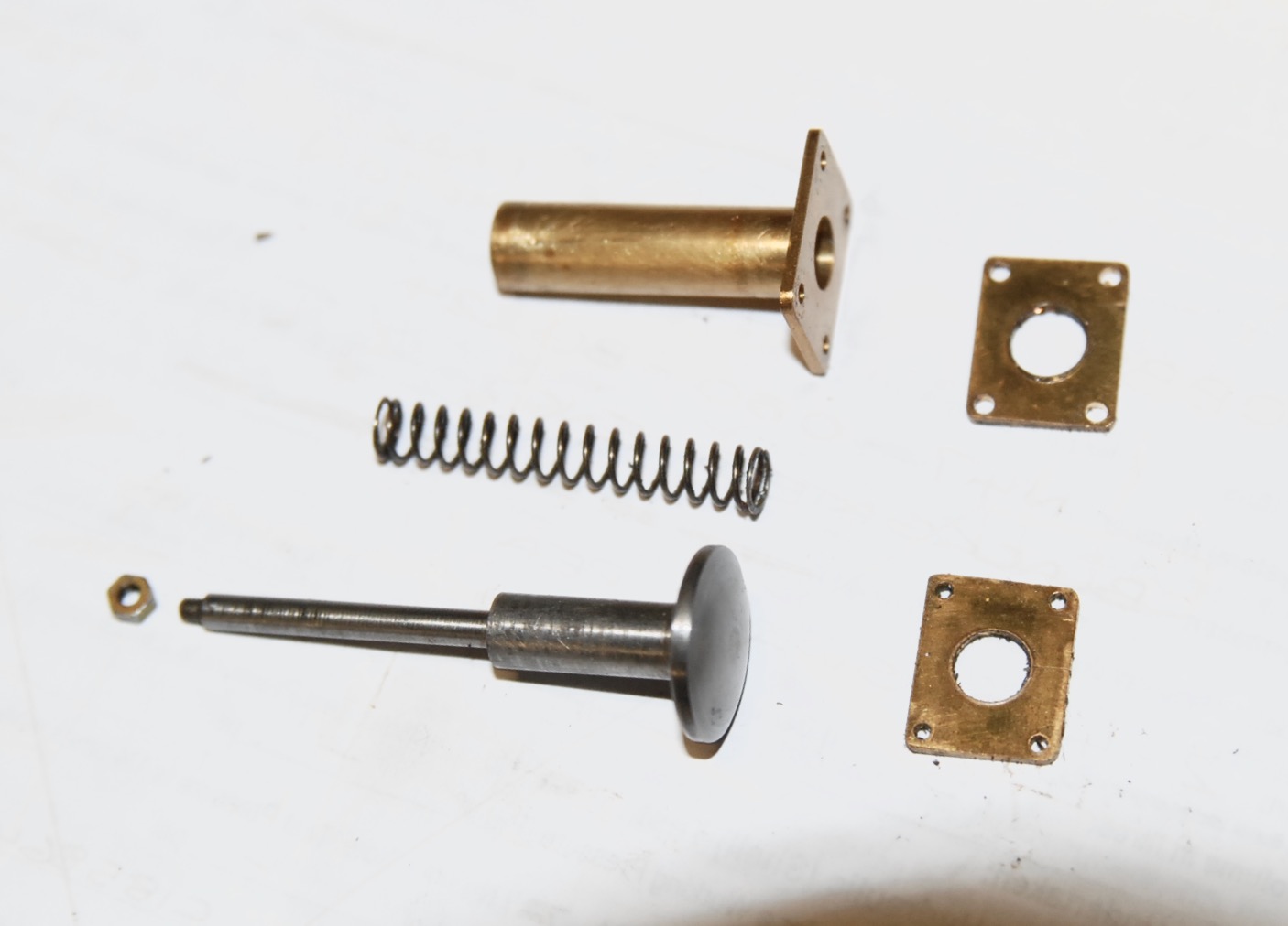
That's enough of the history and so down to these miniature buffers
themselves. You can see in one of the photos the different variants
stripped down to their component parts. The parallel ones follow normal
design with the buffer shank counterbored to accept the spring. A
threaded retaining pin is fitted from the rear and passes through the
stock, spring and shank before screwing into the back of the buffer
head. The slotted head of this pin travels in yet another counterbore in
the back of the stock. Incidentally, it took nearly as long to make and
fix the footsteps as it did to machine the stocks and heads!
The tapered buffer's construction though is something, that I at least,
have never seen before. There is a threaded bronze bush which slides
over the buffer shank and screws into the buffer stock. There is a
travel stop-collar which prevents the head/shank dropping out of the
bush fixed with a small screw to the back of the shank. The spring
merely pushes over this screw-head and the shank/spring/bush assembly is
then compressed into place and retained by screwing the threaded bronze
bush into the nose of the stock. It works well but is over complicated;
also, if ever the threads were to seize it would be very difficult to
get it all apart.
You may be wondering why there is a photo of a piece of rusty old steel
included. Well this is all that remains of the length of bar from which
the heads and stocks were machined. It had been loitering in my stash
for many years and now, at long last, it has got it's five minutes of
fame. One of my life's simple pleasures is to take an old grotty piece
of metal, put it in the lathe and then take a skim off it to reveal
fresh, shiny, virgin material underneath, sad I know, but there you are.
Well that's it for now, I've gone on long enough, besides which I'm in
imminent danger of running late for my pilates class, so I'll close by
saying that without realising it I've become somewhat of an aficionado
regarding buffer design. It's also painfully obvious that I need to
ditch the anorak and get out more often.
Ah yes, before I forget; when KE2 was delivered it came with a box of
bits 'n' pieces, the contents of which will be shown as this project
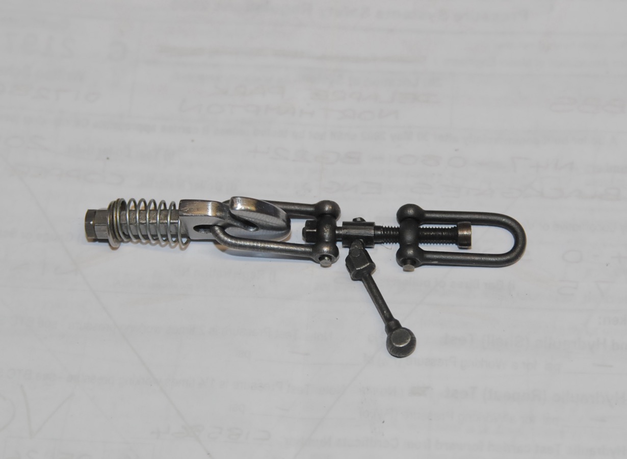
advances. One such item was a correct GWR pattern screw-link coupling
and hook supplied by Polly Engineering, and it's a little belter,
especially the pivoted tommy-bar. I dread to think how long it would
take to make one. The faded label on the packet shows a price of
£21.40p. I don't know when it was purchased and I've been unable to get
onto Polly's website to get a current price (I keep getting the dreaded
'404' message) but Blackgates Engineering do a similar hook and coupling
at £53.58p including VAT but excluding postage. WOW, that's inflation
for yer. I've machined a normal clevis for actual passenger haulage and
it cost me nowt. That's tight-fistedness for yer!
01/12/2023
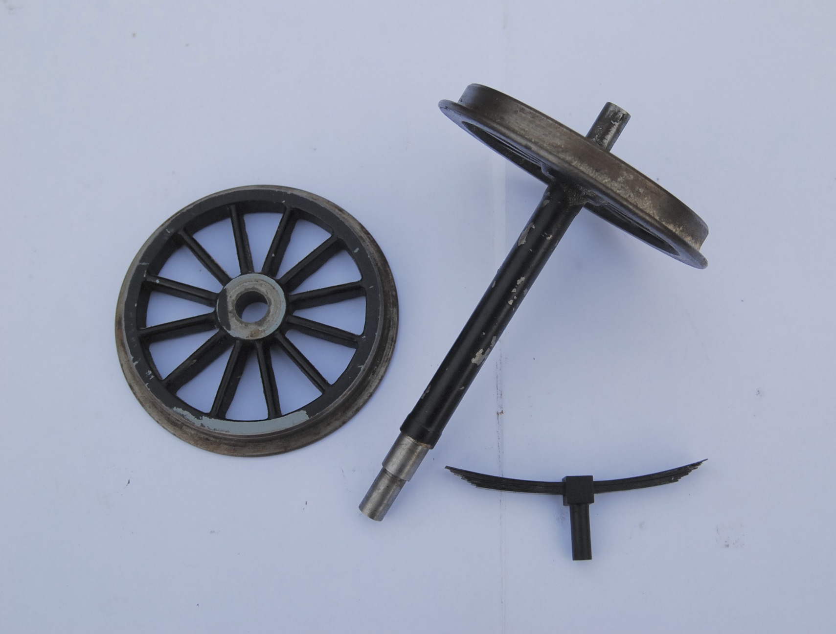
The chassis is now ready to have the running-gear fitted. Having two
chassis there was a choice of two wheel-sets and two sets of working
leaf-springs. As can be seen one wheel-set came with a single wheel
laying loose due to a press-fit failure. Now even though the famous
American opera singer, Kenny Rogers, had a massive hit with "You've
Picked a Fine Time to Leave Me Loose Wheel" that's not a scenario I wish
to face out on the track (or anywhere else for that matter) and so
doubting the integrity of the remaining five the alternative wheel-set
was chosen. It's wheel-castings, although having been machined and
fitted to the axles, required some 'flash' to be removed along with
visible moulding lines, but then nothing that some attention with a file
couldn't sort out. In the same photo a leaf-spring from the 'plain'
chassis can be seen, and whilst no doubt it functions very well it looks
ghastly, so these springs were also ignored in favour of the other set.
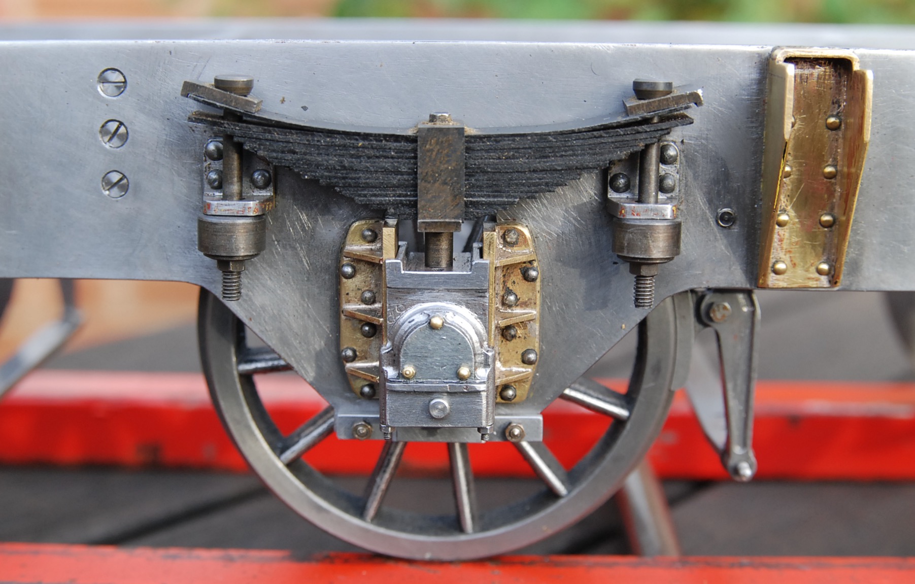
There is a close-up shot of an assembled axle-box, spring and wheel
purely to show the detailing on the axle-boxes. Sadly my photography
doesn't do them justice for they are truly superb having end
cover-plates and studs and simulated upper and lower axle-box sections,
again with dummy studs and nuts. In reality these miniature axle-boxes
have been machined in one piece from steel and have a bronze
axle-bearing fitted from the rear. They weren't quite complete though in
that centrally, on the lower front face of the 'box, was a hole. This
must have been intended for the fitment of an oil-pot, brass with a
hinged lid in full-size, but to make these would have taken too long so
a headed plug was turned and press-fitted in, just to fill the hole up.
A functional oil-hole has been drilled in the top of the 'box for axle
lubrication.
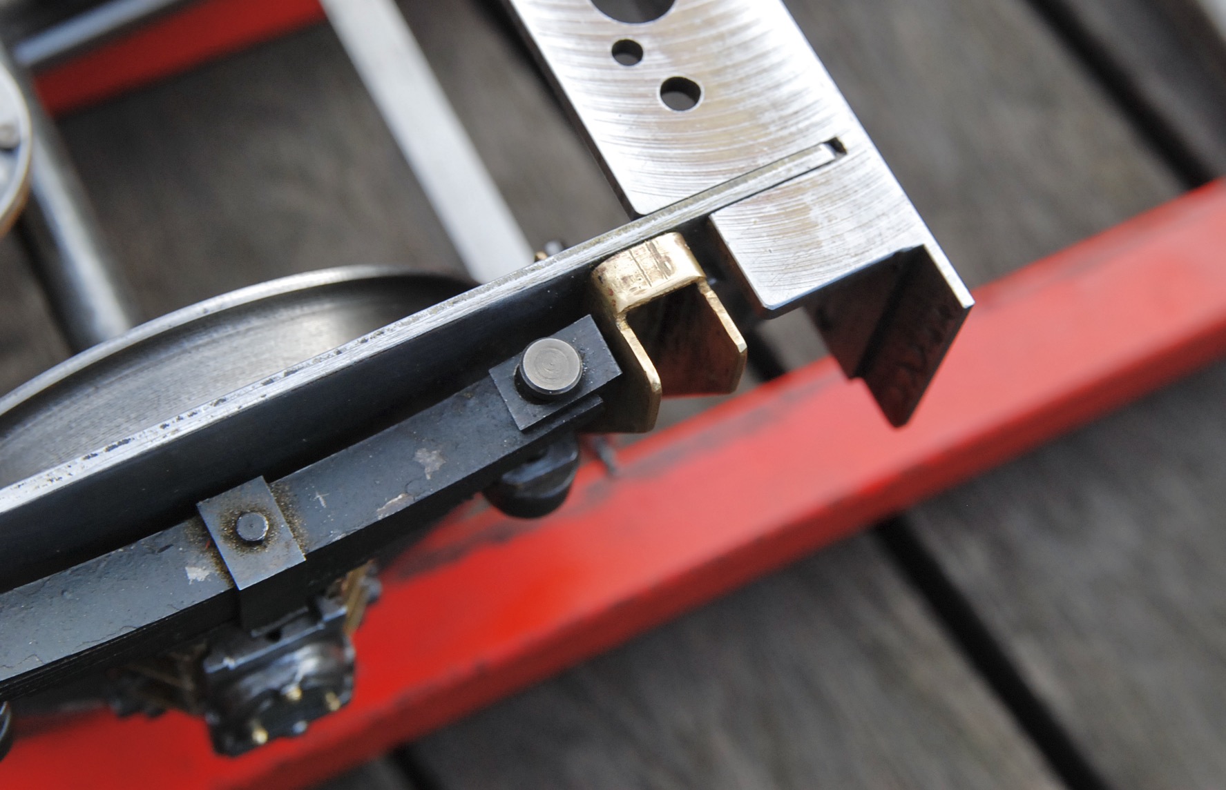
The spring assemblies appear painted but in actual fact have been
chemically blacked, and rather poorly at that, so will indeed require
painting. It also became apparent that these springs could never have
been fitted due to the fact they were too long to fit the rear axle
location, the end of the springs conflicting with the brass tank-support
brackets riveted to the frames. A photo shows just how close the springs
come to these brackets even after the ends of the springs had been
shortened by nearly 2mm.
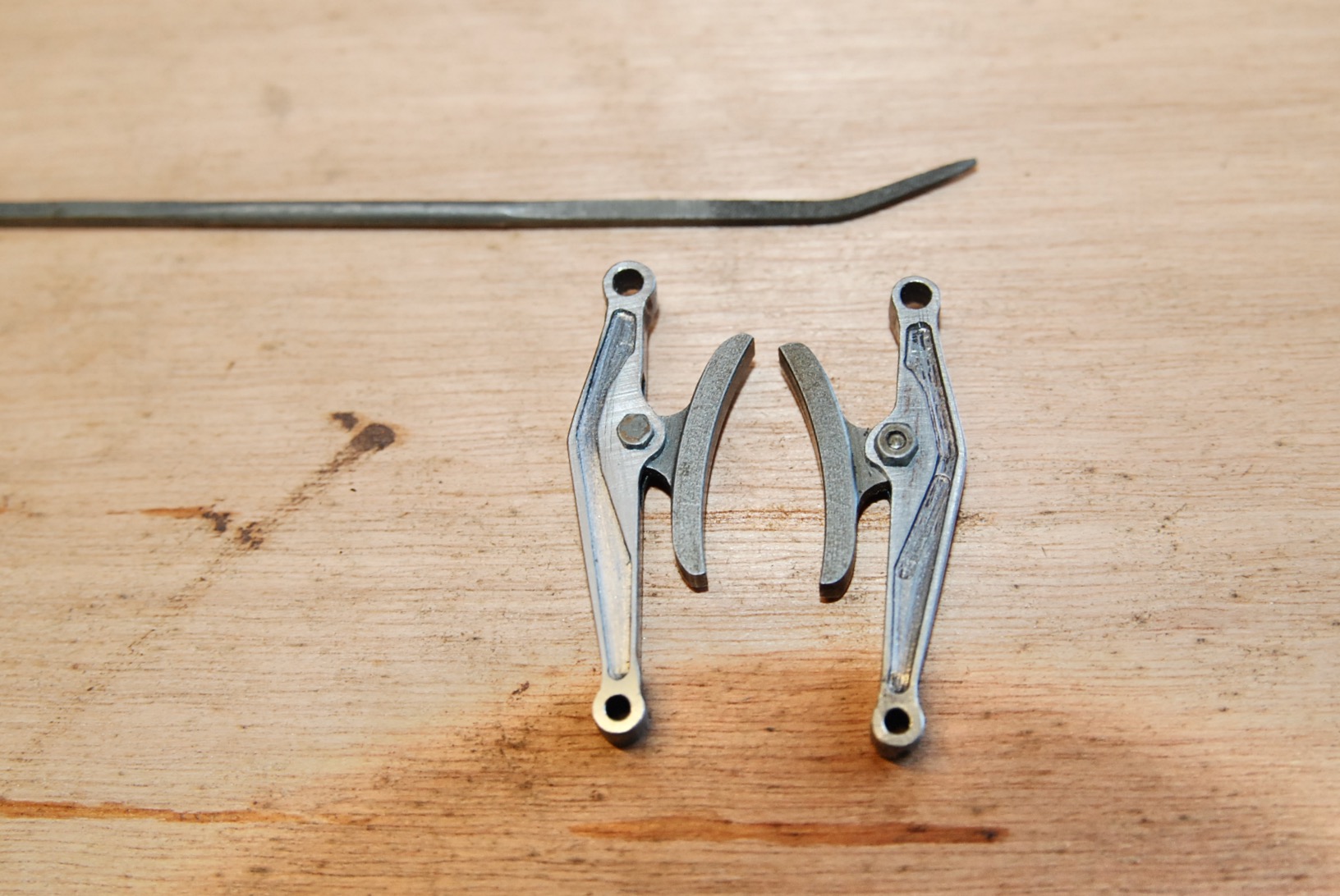
Due to a lack of space it was advantageous to fit the brake-hangers and
beams before the wheel-sets went in. One brake-beam was unfortunately
bent and one of its end-pins, which locate in the brake-hanger lower
hole, had sheared off. So the beam was straightened, a new pin machined
and the broken stub remaining in the beam was carefully drilled out. The
new pin was then bonded in with Loctite retainer.
Now the builder had gone to a great deal of trouble to mill recesses
into the side-faces of the hangers to replicate the appearance of the
cast full-size articles using a 3/32" dia. cutter. This required six
passes to be made in order to produce the shape required. Sadly though
some of these passes varied in depth which spoilt the appearance
somewhat. You can see in the photo the difference between the 'as
received' condition on the right of shot and the smoothed version on the
left. This smoothing was easily achieved using a 'riffler'. If anyone
new to the hobby doesn't know what a riffler is it's simply a file with
a bend in it, the one used in this instance being shown top of shot.
They are available in all shapes and sizes to suit the job in hand, this
particular riffler having a tapered square cross-section. The bend
allows access to concave surfaces which a standard straight file will
not.
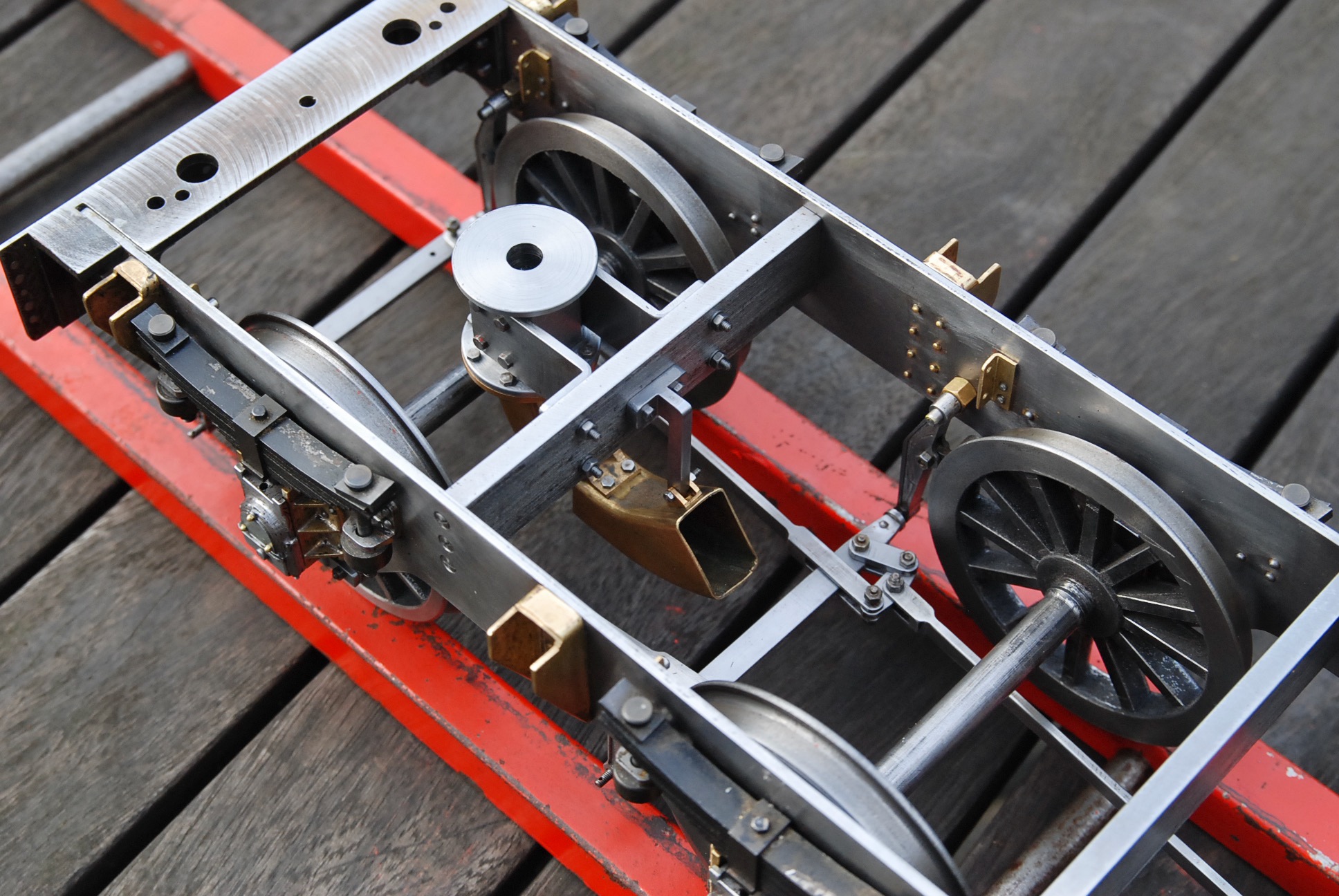
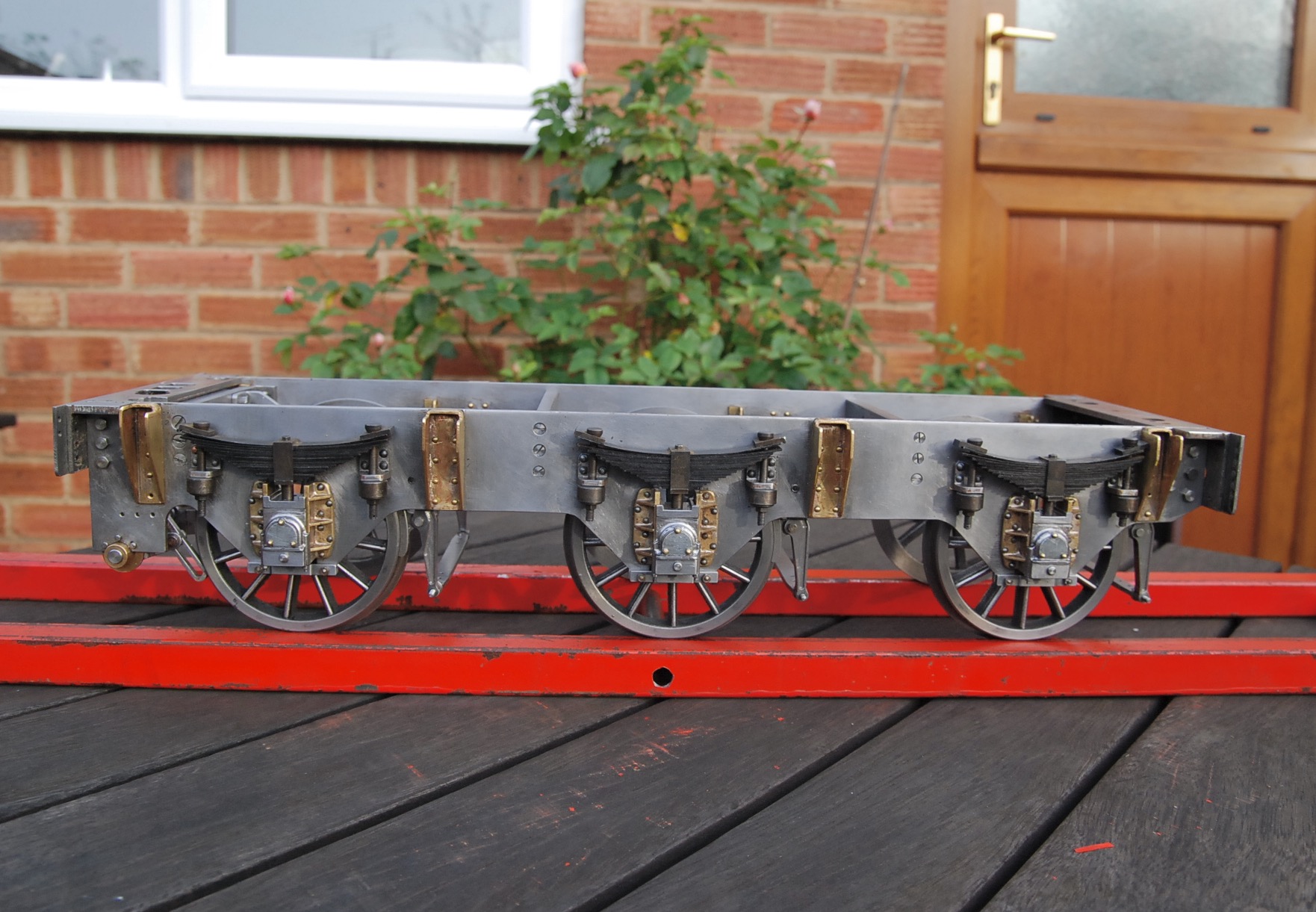
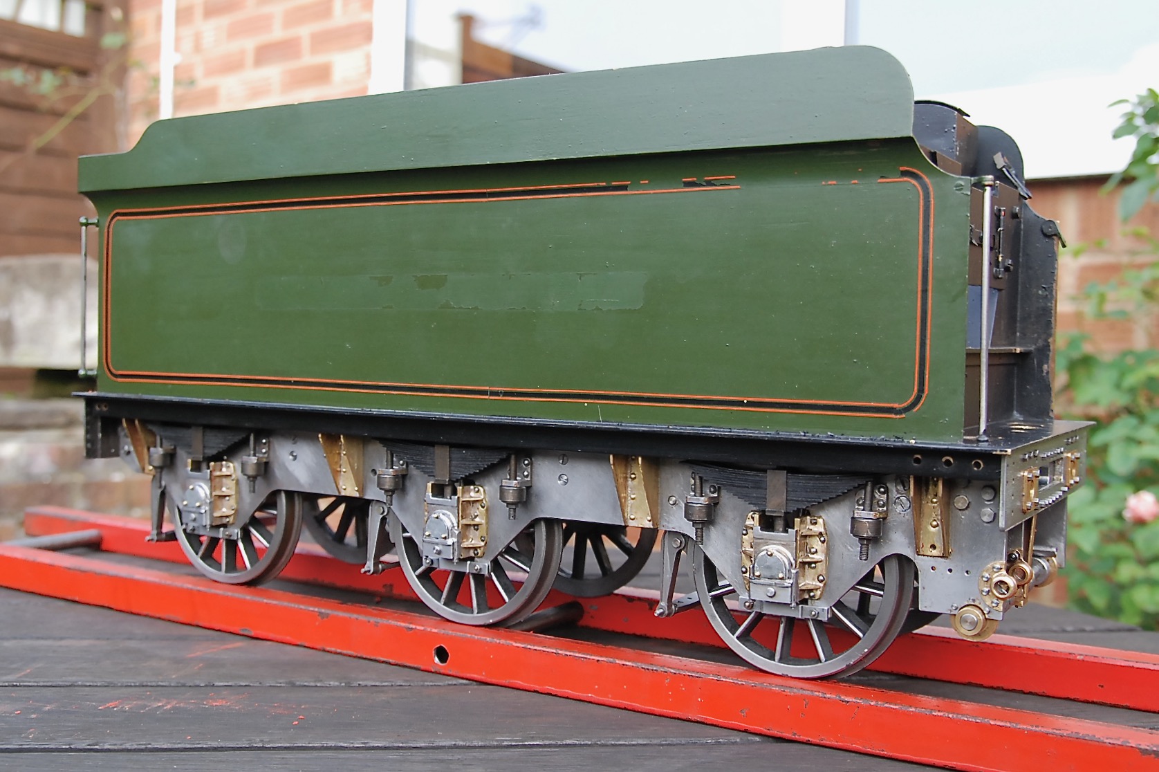
So after a lot of fiddly work you can see the chassis is now sporting
all six wheels etc. and I'm happy to report it rolls very nicely. The
springs give a nice firm suspension, although they've yet to be
adjusted. Finally, despite the tatty paintwork which will need to be
removed, I couldn't resist the temptation to fit the tank, just to get a
sense of the finished vehicle. The verdict? NICE!
|
|
08/12/2023
Having previously erected the brake-hangers and beams the next logical
step is to complete the brake-gear.
Another delight extracted from the bits 'n' pieces box is this vacuum
brake-cylinder, a faithful reproduction of the full-size article. It was
stripped down in order to remove the paint and revealed a functioning
piston and piston-rod gland, plus a threaded pipe connection in the top
cover, so I assume the builder intended it to work. From experience,
powered brakes on locos this small are just a gimmick as all they do is
lock the wheels up due to the vehicle's relatively light weight, so with
this in mind no attempt will be made to get the cylinder to work, it is
purely for aesthetic purposes. A pair of simple folded brackets hold it
in position and the trunnion pins allow it to pivot when the hand-brake
is operated. Now the hand-brake WILL be functional and used as a means
of stopping the loco rolling off the steaming-bays! The hand-brake
operating column will need alteration before it can be fitted but that
task can wait until another time.
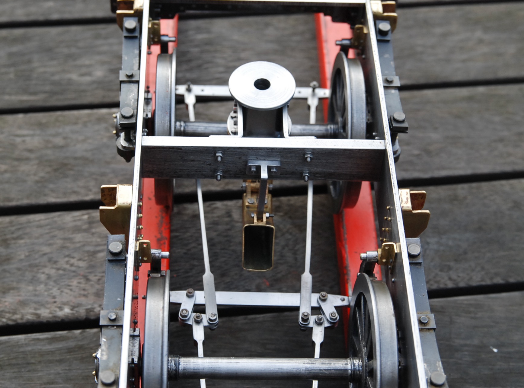
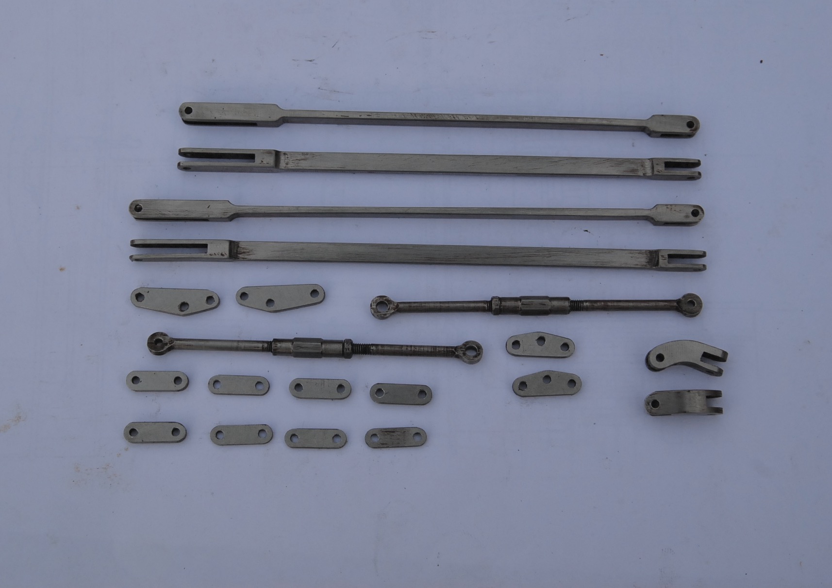
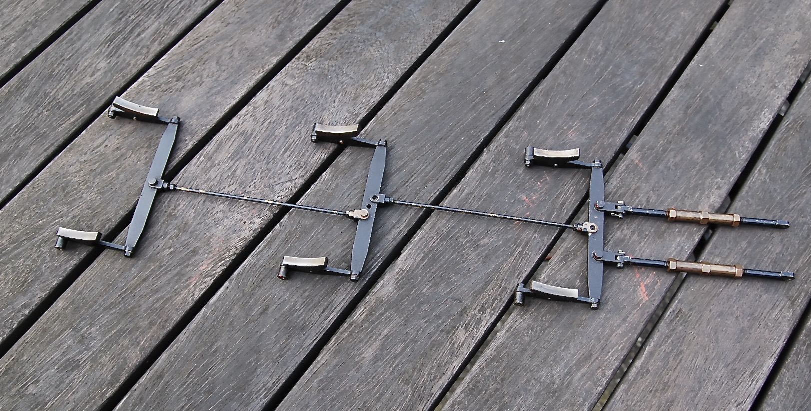
The builder had opted to produce a 'compensated' brake pull-rod
arrangement, as per full-size, which gives an equal pull on each of the
six brake-blocks, and these rods and links are shown prior to assembly.
The rods have the correct rectangular cross-section and incorporate the
end clevises, all machined from solid. The adjusters are threaded
left-hand one end and right-hand the other so do not need removing every
time an adjustment is made. Purely for comparison there is a shot of the
brake pull-rods from the 'plain' chassis which have been made to a much
simpler non-compensated design.
|
|
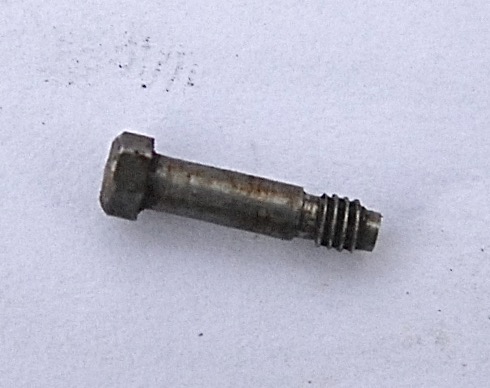
In addition to the scale pull-rods etc. the bolts, which hold the
links/rods together, are of the 'fitted' variety. Again, for any
newcomers not knowing what a 'fitted' bolt is, it's one that has its
plain shank machined to an accurate fit in its intended hole, sometimes
with zero clearance, which then gives the bolt the same properties as a
solid dowel. This type of bolt could be found on full-size locos holding
cylinders, horns and motion plates to the frames as well as many other
stressed locations. There is a shot of one of these miniature bolts
which are around 1/2" long with 3/32" dia shanks and threaded 8BA. They
all sport a small undercut between thread and shank and the hexagonal
heads have been machined to 10BA spec. across the flats. Anyone else
(myself included) would have just used standard 'off the shelf' 8BA
bolts and nuts, so to machine these little bespoke beauties shows
dedication.
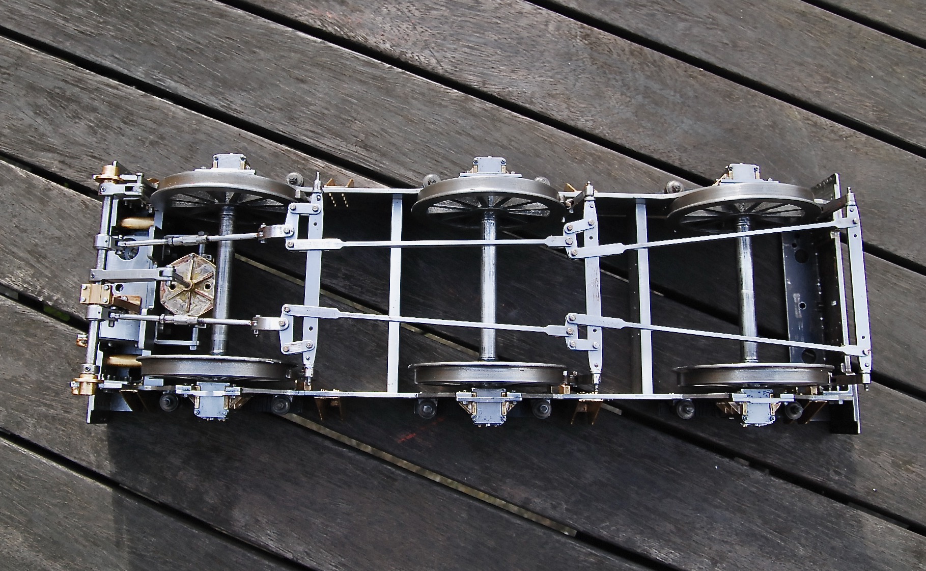
Finishing up, you can see a shot of this brake-gear assembled to the
chassis. I won't lie, it took a bit of fathoming out how it all went
together, but go together it did and when the brake-cylinder is
'activated' all six wheels experience a similar amount of drag. It's a
pity this brake-cylinder will be virtually invisible once the
tender-tank is fitted, and some may say "why bother then", but for me
it's just pleasing to know that it's there!
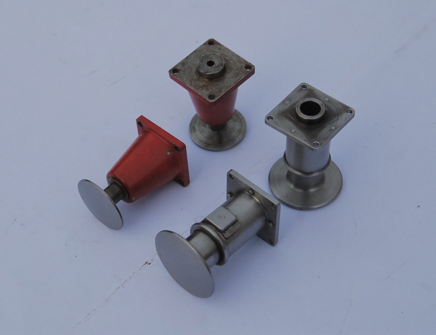
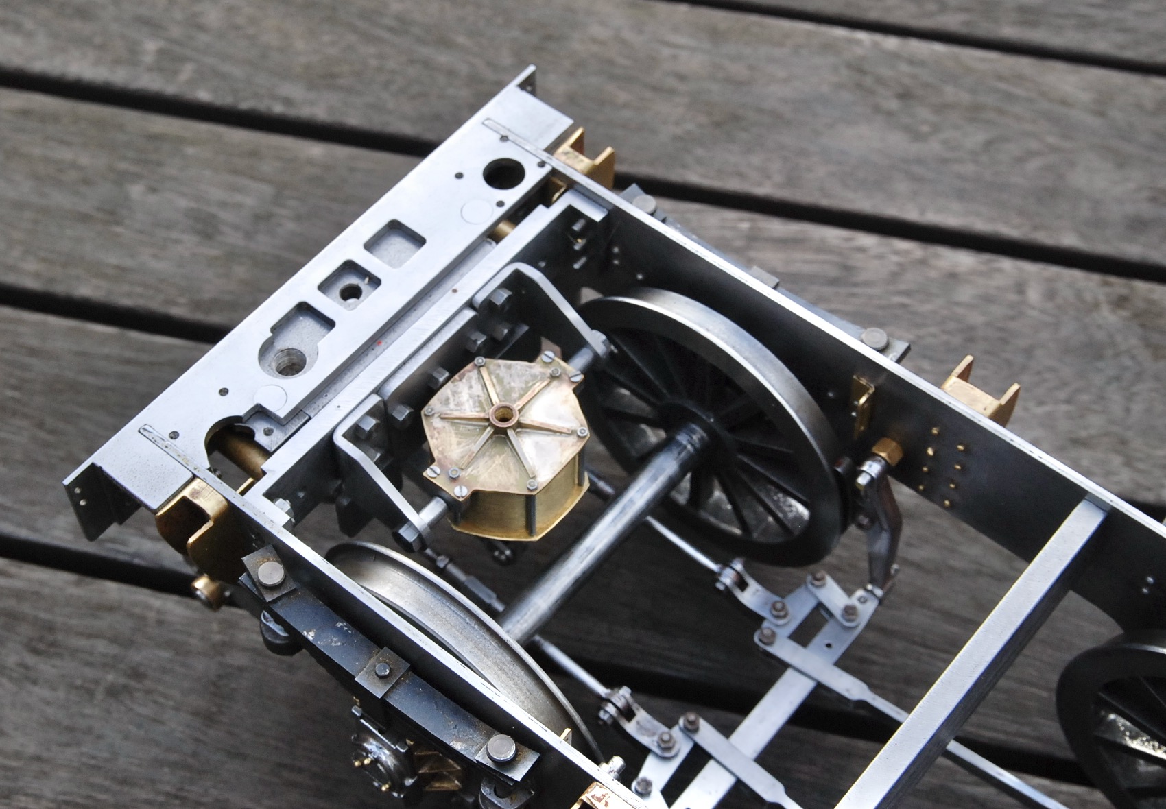
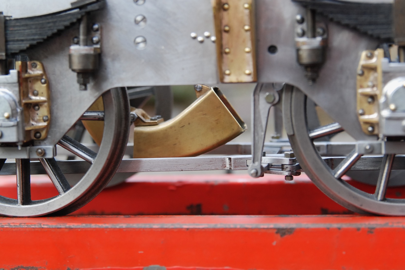
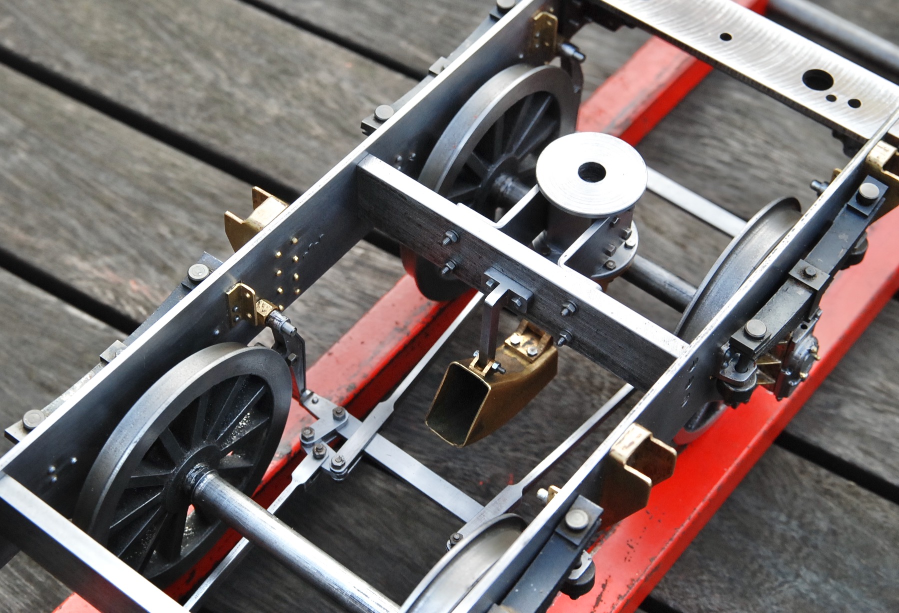
14/12/2023
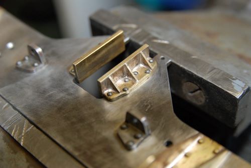
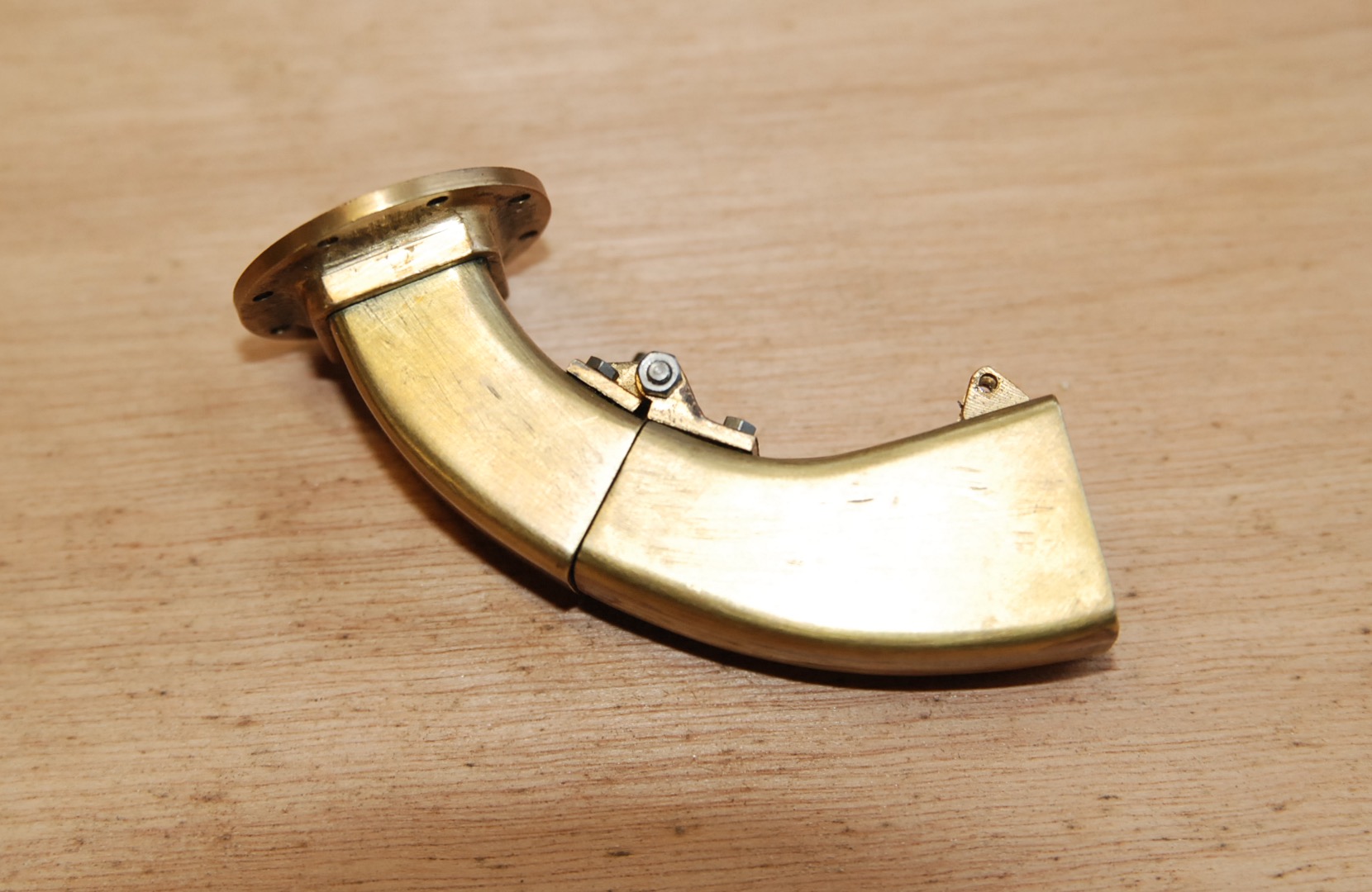
Once again delving into the 'bits 'n' pieces box' (the gift that keeps
on giving) the beginnings of a water pick-up scoop were discovered.
There were three separate brass components as shown: one fixed and one
hinged scoop section and a connecting flange. These items were assembled
and the decision was taken to complete the job.
Now when I say "complete the job" I mean only as far as mounting the
scoop to the chassis. Although it would be straightforward to make the
scoop fully operational it would be a pointless exercise as I doubt
we'll ever get working water-troughs on the elevated track; plus despite
being be far too young (obviously) to ever witnessing full-size
water-troughs in action, archive photographic evidence shows that the
driver in 'our' gauges would get rather wet. The grease-top hat and blue
cotton jacket would have to go and be replaced by sou'wester, cape and
waterproof underpants, not a prospect to be relished!
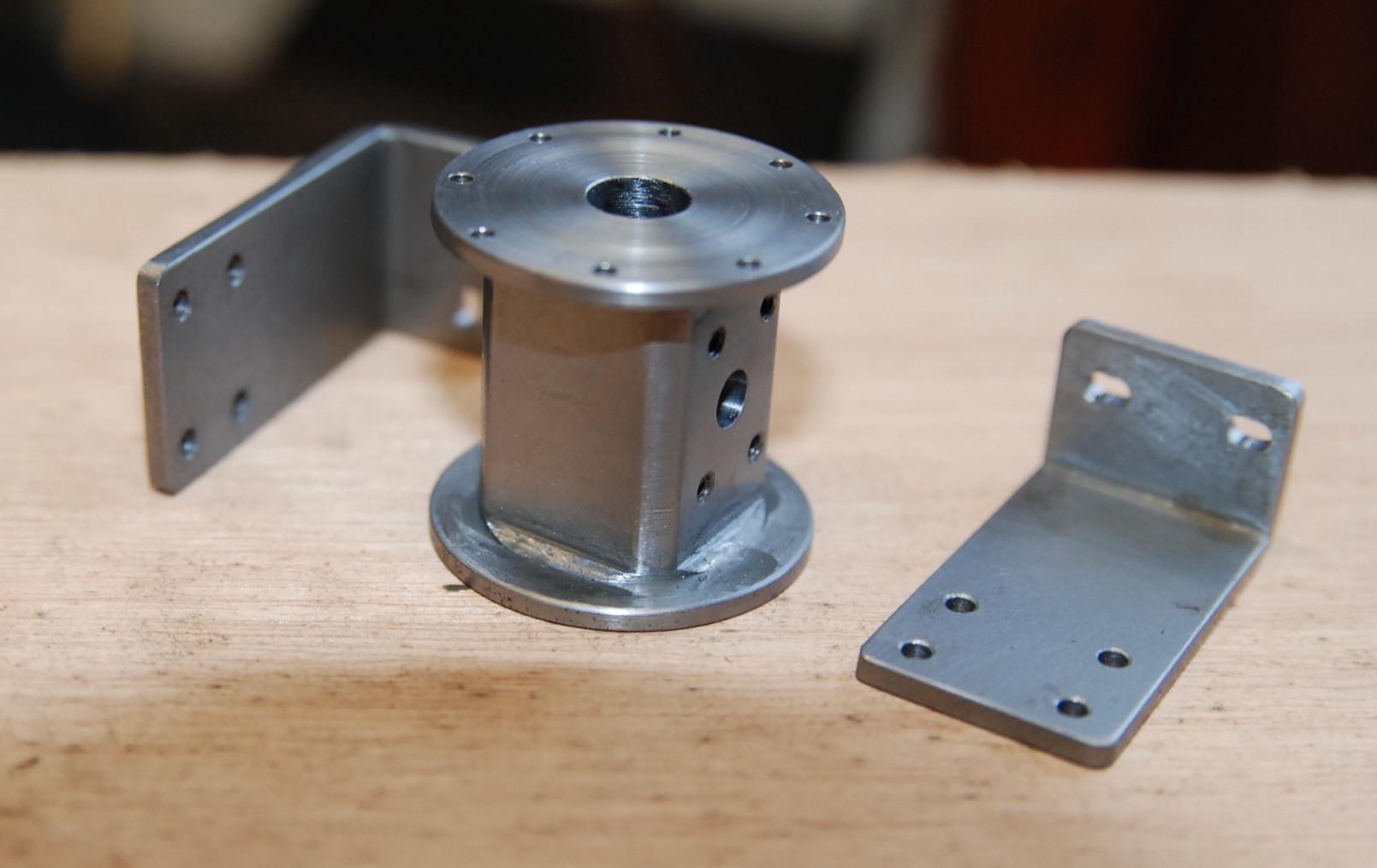
In order to mount this scoop a couple of steel brackets were folded up
and a mounting-block machined to the same section as the flanged brass
connecting-piece. Once fitted together the resulting assembly was then
bolted to the rear frame-stay and a 'T' bracket made to retain the scoop
in the raised position. Even with the scoop fully lowered it would still
miss our track sleepers, but it's best not to take any chances. The
steel mounting-block is adjusted to stop just short of the tender floor
and will only be visible by laying on one's back on the steaming bay
floor. I'll admit to being quite chuffed with how this particular
feature has turned out. It has also dawned on me that this dummy
water-scoop and myself share a couple of similarities insofar as we both
look fantastic yet serve no useful purpose.
To my mind items such as this scoop, the brake cylinder and buffers etc.
are things of beauty in their own right. Imagine, if they were reduced
in size to say 12mm or so, cast in sterling silver and hung on a piece
of scale whistle-chain they would make the perfect model-engineers'
charm-bracelet. Now I ask you, what effeminate model engineer (and I've
met a few over the years) wouldn't want one of these for Christmas; it
could be a nice little earner. Watch this space!